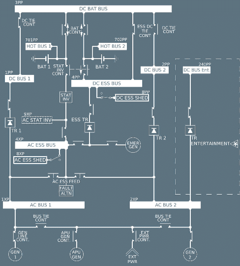
Understanding how the A320 electrical system manages its power sources is critical for pilots and engineers alike. This article breaks down the source priority and redundancy built into the aircraft, highlighting the importance of each component for flight safety. The A320 employs a sophisticated network of electrical bus bars and systems to ensure a reliable power supply under various operating conditions. The essential bus (ESS bus) plays a pivotal role in this configuration, as it is automatically supplied by the emergency generator when needed.
Additionally, the AC essential bus (AC ESS bus) is crucial for providing power to critical systems, converting AC power into DC power where necessary for specific applications. The system includes multiple electrical buses such as the DC battery bus (DC BAT bus) and the DC essential bus (DC ESS bus), which work in tandem to deliver power effectively.
In scenarios where both AC bus 1 and AC bus 2 are lost, the emergency AC power can be supplied through the auxiliary power unit (APU) which can provide emergency electrical power through its generator (APU GEN), and RAT (Ram Air Turbine) which automatically deploys from the left side under the wing, powering blue hydraulic line and emergency generator.
Understanding the operation of pushbuttons and bus switches, including the bus tie pushbutton switch, is vital for managing the electrical system during flight, ensuring that power is routed correctly and that the battery line contactor operates as intended. This comprehensive overview aims to equip you with the knowledge needed to navigate the complexities of the A320’s electrical source priority system.
 Overview of the A320 Electrical System
 Overview of the A320 Electrical System
Short overview of the A320’s electrical system architecture
The Airbus A320 electrical system is intelligently designed around a three-phase 115/200 V, 400 Hz constant-frequency AC network and a 28 V DC network. The primary power source is AC power under normal operations. Aircraft systems can tolerate transient variations in voltage or frequency, showcasing the robust nature of the system.
Importance of source priority and redundancy in flight safety
Source priority and redundancy are vital for the safe operation of the Airbus A320. Redundancy ensures that critical systems can continue to function even if a primary power source fails. Without proper source priority in the electrical system, the aircraft is at risk of electrical power loss.
Primary Power Sources and Their Priority
GEN 1 and GEN 2 (engine-driven generators)
The Airbus A320 is equipped with two AC engine generator systems, GEN 1 and GEN 2, one on each engine. These generators supply up to 90 kVA of 115/200 V, 400 Hz, three-phase AC power. Each engine generator is managed by a Generator Control Unit (GCU), which ensures proper voltage and frequency output and controls the generator line contactor.
APU generator
The Airbus A320 is equipped with an APU generator, a third generator, powered by the APU. It provides the same output as the engine generators and can substitute for either or both of the engine-driven units. When the engine generators are not running, the APU generator becomes crucial.
External ground power
External power can provide electrical power to the aircraft while on the ground, allowing systems to be tested without running the engines or the APU. This is particularly useful during maintenance checks or while preparing the aircraft for flight, using the external power connector.
Priority order:
The source selection hierarchy for the aircraft’s electrical network prioritizes different power sources. The selection order is as follows:
- Engine-driven generators (GEN 1 and GEN 2)
- APU generator
External power is the last priority. Automatic switching follows this order, but manual selection can override it.
How External Power is Handled
Plug-in location and conditions for use
The external power plug-in location is usually found near the nose gear, allowing ground crews easy access. External power can be utilized when the aircraft is on the ground and the engines are not running. There is also a control panel in the cockpit to allow use of external power.
Role of the GPCU and GAPCU
The Ground Power Control Unit (GPCU) protects the electrical network via the external power contactor. In some configurations, the Ground and Auxiliary Power Control Unit (GAPCU) is utilized, which regulates the APU generator’s voltage and frequency, managing both APU and external power connections.
Limitations (only usable on the ground)
Ground commercial power is designed to be utilized only on the ground, which means that it has a lower priority compared to onboard generation systems. This ensures that the electrical power to the aircraft is controlled via the aircraft and does not rely on external sources during flight.
APU Generator Role in Source Hierarchy
When and why it takes over
The APU generator often takes over when the engine generators are not available, like during ground operations or in-flight single-engine situations. When the AC bus 1 or AC bus 2 loses power, the APU generator can automatically supply the AC bus. The aircraft electrical system utilizes this to ensure no loss of service occurs.
Output specs matching engine generators
The APU generator delivers the same output specs as the engine generators. It produces 90 kVA of three-phase 115/200 V, 400 Hz AC power, which is crucial for maintaining consistent electrical power throughout the aircraft electrical system. This ensures seamless transitions between power sources without voltage or frequency fluctuations.
Use during ground operations or single-engine taxi
During ground operations or single-engine taxi, the APU generator serves as an efficient power source. Instead of running an engine generator at high thrust, the APU generator supplies the aircraft electrical system. This reduces fuel consumption and wear and tear on the engines. The APU also provides power to the AC essential bus.
Emergency Power Systems in the A320
Blue hydraulic circuit–driven emergency generator
The Airbus A320 features an emergency generator driven by the blue hydraulic system. In the event of complete AC generator failure, the emergency generator activates automatically. This emergency generator is critical for maintaining power to essential systems during critical moments. The aircraft electrical system relies heavily on this redundancy.
When it activates (loss of AC power from all generators)
The emergency generator activates upon the complete loss of AC power from all primary generators. If both engine generators and the APU generator fail, the electrical power to the aircraft switches to the emergency generator. A loss of all AC buses triggers the emergency electrical network. It’s a key safety feature in the A320 electrical system.
What systems it powers (AC essential bus, avionics)
The emergency generator powers critical systems, including the AC essential bus and essential avionics. This ensures that essential navigation, communication, and flight control systems remain operational. By providing power to the essential bus, the emergency generator stabilizes the AC electrical network and DC electrical network.
GCU functions: speed, voltage, startup
The Generator Control Unit (GCU) manages the emergency generator’s operation. It controls rotational speed, voltage output, protection contactors, and startup sequencing. The GCU ensures the emergency generator produces stable and reliable AC power, maintaining the electrical network. The pilot must ensure voltage is within range.
Static Inverter Functionality in Battery-Only Operation
Converts DC to AC from Battery 1
The static inverter converts DC power from Battery 1 into AC power. It provides 1 kVA of single-phase 115 V, 400 Hz AC power. In battery-only operation, this conversion is essential for powering AC essential systems. The Airbus A320 electrical system relies on the inverter to convert DC to AC.
Activation conditions: aircraft speed >50 kt or BAT 1+2 ON <50 kt
The static inverter activates under specific conditions. It turns on when the aircraft speed exceeds 50 knots or when both Battery 1 and Battery 2 are ON with the aircraft speed below 50 knots. These conditions ensure electrical power to the aircraft at critical times. The Airbus A320 electrical system depends on these parameters.
Supplies AC essential bus
The static inverter supplies AC power for critical loads on the AC essential bus. This ensures that vital systems, such as navigation and communication equipment, remain operational during emergency situations. By providing a stable AC power source from the battery, the static inverter supports flight safety and systems.
Battery Backup and Hot Bus Protection
Two 23Ah main batteries
The Airbus A320 features two main batteries, each rated at 23 amp-hours. These batteries provide essential backup power to the aircraft electrical system, especially during ground operations and emergency situations. Each battery ensures that vital systems can continue to function even when other power sources are unavailable, protecting the hot buses.
BCL control and monitoring
Each battery is supervised by a Battery Charge Limiter (BCL). The BCL monitors charging conditions and controls the battery’s contactor. The BCL prevents overcharging and ensures that the batteries are maintained in optimal condition. This is a critical aspect of the electrical network because it ensures reliable battery power is available at all times.
Support for hot buses, inverter, emergency power
The A320 features two main batteries, each rated at 23 amp-hours, which are permanently connected to their respective hot buses. This allows for uninterrupted electrical power to the aircraft for critical systems. In addition to supporting the hot buses, these batteries also supply power to the static inverter and emergency power systems when needed.
Real-World Scenarios and Failover Logic
What happens when one generator fails?
When one engine generator fails, the Airbus A320 electrical system automatically compensates to maintain electrical power to the aircraft. The remaining generator picks up the load, ensuring no loss of critical systems. The bus tie contactors close to balance the electrical network and to re-establish the AC bus connections.
How the aircraft reconfigures power sources automatically
The aircraft automatically reconfigures power sources to maintain electrical power to the aircraft via a variety of parameters. The source priority logic selects the most appropriate available power source based on availability and load demands. This reconfiguration ensures continuous operation of essential systems, minimizing power gaps.
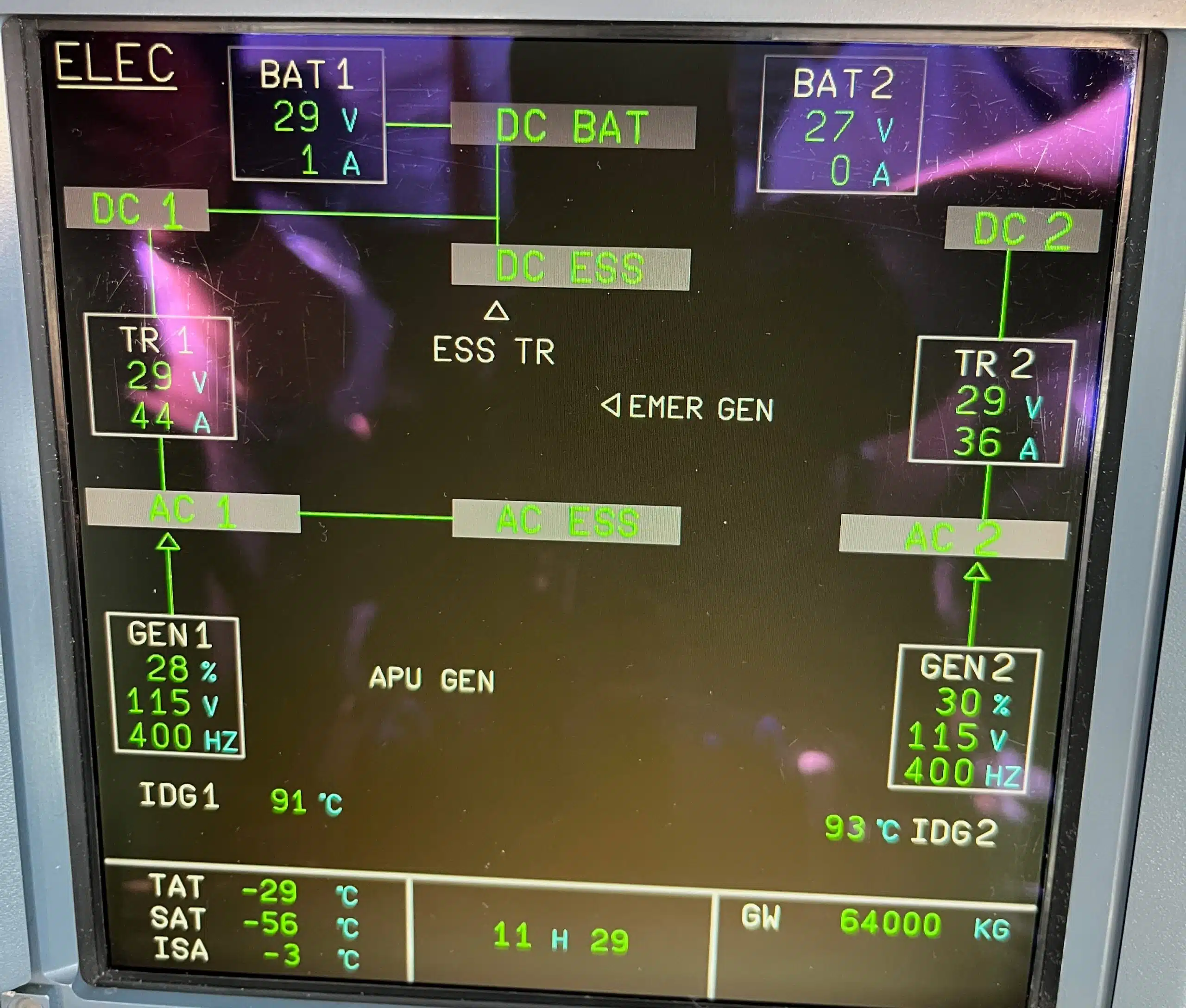
What pilot sees on ECAM
In the cockpit, the pilots receive real-time information about the electrical system status via the ECAM (Electronic Centralized Aircraft Monitoring) display. Any generator failure, bus transfer, or abnormal electrical conditions are immediately displayed. This allows them to monitor the electrical power to the aircraft and take appropriate actions if needed, such as feeding the AC essential bus.
 Can the APU supply the entire aircraft?
 Can the APU supply the entire aircraft?
Any one engine generator can supply power to the full aircraft electrical system, with the exception of the DC Entertainment bus. Two power sources (such as two generators or generator plus ground power) are required to supply the DC Entertainment bus fully. On the ground, however, either the APU generator (if not overloaded) or external power alone is sufficient to meet that requirement.
Summary: Why Source Priority Matters
Ensures flight safety and system continuity
Source priority is crucial for flight safety and system continuity in the Airbus A320. By ensuring that the most reliable power source is always selected first, the electrical network can maintain uninterrupted operation of critical systems. The automatic prioritization of power sources ensures that the essential bus is always powered.
Prevents power gaps during generator loss
The source priority system prevents power gaps during generator loss by immediately switching to an alternative power source. The APU generator or emergency generator seamlessly takes over, ensuring no interruption to essential systems. This rapid switchover capability is crucial for maintaining stable electrical power to the aircraft.
Essential for Comprehending Airbus Fly-By-Wire Design Principles
Grasping electrical source priority is vital for understanding the Airbus fly-by-wire design principles. The fly-by-wire system depends on a reliable and consistent electrical power supply. Automatic selection of power sources and redundancy are integrated into the A320 electrical system, which includes AC and DC buses, ensuring seamless operation of the fly-by-wire controls.
Frequently Asked Questions
What is the function of IDG in A320?
The Integrated Drive Generator (IDG) on the Airbus A320 serves as the primary AC power source, converting mechanical engine power into stable, constant-frequency electrical energy. Each engine has its own IDG (GEN 1 and GEN 2), which delivers 115/200 V three-phase AC at 400 Hz to the aircraft’s electrical network.
The IDG combines:
- A generator, which produces electricity - A constant speed drive (CSD), which ensures the generator spins at a constant speed, regardless of engine RPM
This configuration guarantees that the output frequency remains fixed at 400 Hz, a critical requirement for the aircraft's systems. The IDGs are managed by Generator Control Units (GCUs), which regulate voltage and frequency and protect the network by controlling the generator line contactor.
In summary, the IDG ensures a stable and reliable AC power supply, which is essential for flight control computers, avionics, lighting, fuel pumps, and other critical systems.
Are they separate buses from AC/DC ESS?
Yes, the Airbus A320 electrical system includes several separate electrical buses, with dedicated essential buses (AC ESS and DC ESS) being part of a prioritized subset designed to maintain critical operations during power failures.
Key bus categories include:
- AC BUS 1 / AC BUS 2 – Primary distribution buses for AC power - DC BUS 1 / DC BUS 2 – Primary DC distribution via transformer rectifiers - AC ESS BUS – The AC Essential Bus supplies power to essential flight systems (e.g., parts of EFIS, ECAM, flight control computers) - DC ESS BUS – The DC Essential Bus supports key DC-driven systems in the event of generator loss - AC SHED ESS and DC SHED ESS – These are load-shedding buses, automatically deactivated to preserve battery life during emergency power operations - HOT BUS 1 / HOT BUS 2 – Always energized; connected directly to the batteries, powering items like fire extinguishers and cargo door controllers - DC BAT BUS – Links the batteries to critical systems during full electrical loss - DC ENTERTAINMENT BUS – Dedicated to the In-Flight Entertainment (IFE) system (not flight-critical)
In failure scenarios, automatic bus reconfiguration ensures that essential systems continue receiving power from the APU, emergency generator, static inverter, or batteries.
So yes, there are separate buses beyond just AC/DC ESS, each designed for specific load categories and redundancy paths.