A320 Flight Path Vector Explained for Pilots: Understanding FPV and ILS Approaches
Welcome to a comprehensive guide on the Airbus A320 Flight Path Vector (FPV), often referred to as “the bird.” This guide is designed to help pilots understand and effectively use the FPV, enhancing their flight operations, especially during instrument landing system (ILS) approaches and other critical phases of flight.
Introduction to Flight Path Vector (FPV)
What is Flight Path Vector (FPV)?
On the Airbus A320 Primary Flight Display (PFD), the flight crew can utilize the Flight Path Vector, or FPV, as a critical reference for aircraft control. This FPV symbol, sometimes called “the bird,” provides a visual representation of where the aircraft is actually heading, accounting for both its speed and direction. The flight path vector essentially shows the pilot the aircraft’s trajectory over the ground.
Importance of FPV in Flight Operations
The FPV is particularly valuable during stable flight segments, such as non-precision approach scenarios and visual approaches. In these phases, trajectory guidance relative to the ground is more beneficial than air-referenced stability. By focusing on the flight path displayed by the FPV, pilots can maintain the desired flight path and efficiently manoeuvre the aircraft, especially during the final approach.
Overview of A320 Series and its Flight Path Vector
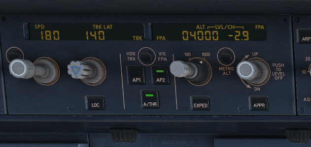
In the Airbus A320 Primary Flight Display, pilots have two main references for controlling the aircraft: the aircraft’s attitude and the Flight Path Vector. The active FCU mode determines which reference takes precedence. When TRK/FPA mode is engaged, the FPV becomes the primary flight reference, displaying track (TRK) and flight path angle (FPA). Conversely, the FPV disappears when HDG/VS mode is active.
Watch: A320 “Bird” Flight Path Vector Explained by a Real Airline Pilot
Still wondering how Airbus A320 pilots use the Flight Path Vector (FPV), also known as “the bird”? Watch this clear and practical explanation by a real-world A320 captain. In this video, Mentour Pilot breaks down the logic behind the TRK/FPA mode, how the bird assists in approaches and visual flying, and what its limitations are during dynamic maneuvers like go-arounds.
This video complements Airbus FCTM guidance and offers a hands-on look at how pilots manage the bird symbol on the Primary Flight Display during real flight scenarios.
Understanding the A320’s Flight Control Systems
Primary Flight Display Features
The Airbus A320 Primary Flight Display (PFD) offers flight crews two primary references for aircraft control: the aircraft’s attitude and the Flight Path Vector (FPV), commonly referred to as “the bird.” Understanding both is crucial for pilots. By interpreting these references, pilots can accurately assess the aircraft’s flight path and make necessary adjustments to maintain the desired flight profile.
How FPV Integrates with Flight Control
The selected FCU mode determines which reference is active. When TRK/FPA mode is selected, the FPV becomes the primary flight reference, displaying track (TRK) and flight path angle (FPA). Conversely, when HDG/VS mode is selected, the FPV disappears and traditional attitude-based references take over. The FPV is computed using data from the Inertial Reference System (IRS) and static pressure sources.
Differences in FPV Across the A320 Series
While the fundamental functionality of the Flight Path Vector remains consistent across the A320 series, subtle differences may exist in its implementation and integration with other systems. These differences can be attributed to software updates, avionics upgrades, and specific airline configurations. Pilots transitioning between different A320 aircraft models should be aware of these nuances to ensure consistent and safe flight operations.
A320 ILS Approaches and Glide Slope Management
Basics of ILS (Instrument Landing System)
An ILS approach is a precision instrument approach that provides pilots with both lateral and vertical guidance to the runway. The glide slope is a crucial component of an ILS, providing vertical guidance. The localizer provides lateral guidance, aligning the aircraft with the runway centerline. Proper use of the ILS allows for safe and accurate landings, especially in low-visibility conditions. The Airbus A320 flight management system supports ILS approaches.
Role of Glide Slope in ILS Approaches
The glide slope (GS) is a radio beam transmitted from the airport that provides vertical guidance to the pilot during an ILS approach. It helps the pilot descend at the correct angle, typically 3 degrees, to the runway. Maintaining the aircraft on the glide slope ensures a safe descent profile, preventing premature descents or flat approaches. The FPV aids in monitoring the glide slope and tracking the glide slope intercept, ensuring a stable approach on the Airbus A320.
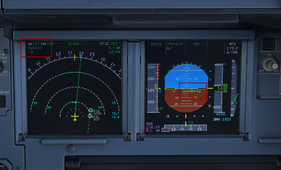
Utilizing FPV During ILS Approaches
During an ILS approach on the Airbus A320, the FPV provides valuable real-time information about the aircraft’s trajectory, particularly during the final approach. The FPV quickly highlights any trajectory deviations or variations caused by wind, which helps the flight crew to adjust the flight path accordingly. The FPV works with GS MINI for shear and gust protection. The FPV symbol’s position relative to the aircraft symbol shows any wind drift, enabling pilots to maintain the approach path effectively.
Lateral Navigation and Flight Path Vector
Understanding Lateral Navigation in A320
Lateral navigation in the Airbus A320 involves managing the aircraft’s horizontal path. The Flight Management System (FMS) plays a crucial role in this, allowing pilots to input flight plans, including waypoints and desired tracks. Effective lateral navigation ensures the aircraft remains aligned with the intended route, especially during approaches and en-route segments. Understanding the interplay between the FMS and lateral control is vital for precise flight path management. The Airbus aircraft’s control panel allows for lateral input.
FPV’s Role in Lateral Control
The FPV gives valuable assistance when flying approaches using FPA guidance. On the FCU, pilots have the option of choosing an inbound track and a descent path angle. Once these are selected, the FPV and the Flight Director (FD) allow for accurately controlling the descent and lateral alignment. This helps ensure that the aircraft remains on the intended flight path. The Airbus FCOM contains information on the effective use of the FPV symbol in conjunction with the flight director bars.
Adjusting Flight Path Vector for Optimal Performance
Fine-tuning the Flight Path Vector is critical for optimal performance on the Airbus A320. During approaches, pilots use the FPV to make small adjustments to maintain the desired flight path angle (FPA) and track. Precise adjustments ensure a smooth and stable approach, maximizing efficiency and safety. The FPV allows pilots to actively correct and adjust bank angle, pitch attitude, and vertical speed for the best performance. Understanding these adjustments is critical for flying the Airbus A320.
Conclusion
Key Takeaways for Pilots
For pilots flying the Airbus A320, mastering the use of the Flight Path Vector is essential for safe and precise flight operations. During visual circuits, the FPV provides valuable visual cues. On downwind, maintaining level flight is ensured by keeping the aircraft’s wings level with the horizon line. Aligning the FPV tail with the track index on the PFD aids in maintaining the desired track. On final approach, achieving a standard 3-degree descent path occurs when the top of the bird’s tail sits just below the horizon and the bottom aligns above the -5-degree pitch marker.
Future Developments in A320 Flight Technology
The future of A320 flight technology promises advancements in flight control systems and navigation capabilities. Enhanced flight management systems (FMS) may integrate more sophisticated algorithms for predictive analysis, optimizing flight path management and fuel efficiency. Integration of augmented reality (AR) and artificial intelligence (AI) may provide pilots with more intuitive displays and decision support tools. These advancements aim to reduce pilot workload and improve overall safety and navigation, especially during challenging conditions.
Resources for Further Study
For pilots seeking to deepen their understanding of the Airbus A320 Flight Path Vector, several resources are available for further study. The official Airbus Flight Crew Operations Manual (FCOM) provides detailed information on the system’s functionalities and operational procedures. Online aviation forums and communities offer platforms for pilots to share their experiences and insights. Additionally, simulator training sessions provide hands-on experience in utilizing the FPV in various flight scenarios. Consulting with experienced A320 instructors and mentors can also be invaluable in mastering the intricacies of the aircraft’s navigation capabilities.