The A320 fuel system is designed to efficiently manage fuel storage and distribution. Fuel storage tanks include inner and outer wing tanks plus the center tank. The left-wing tank supplies fuel to the left engine, while the right-wing tank supplies fuel to the right engine.
When tanks are filled, the system monitors fuel volume to maintain proper center of gravity. Main fuel pumps provide fuel to engines and also fuel to the auxiliary power unit. Engineers regularly check the fuel quantity and related fuel parameters.
The system utilizes fuel lines on both sides of the fuel system to ensure reliability. Fuel vent systems regulate pressure as fuel in each tank is consumed. The design helps allow fuel transfer between tanks when needed.
The process begins with fuel being stored in multiple fuel tanks in the aircraft, primarily the wing tanks and center tank. When the aircraft is ready for operation, fuel pumps activate to supply fuel to the engines and the auxiliary power unit. Initially, fuel from the center tank is consumed first until the center tank is low, after which the system transitions to the main fuel stored in the wings.
The inner workings of the fuel system include tank pumps and jet pumps that ensure proper flow of fuel. The crossfeed valve allows for tank transfer when necessary, while fuel valves regulate the distribution. The fuel management is monitored through the overhead panel and control panel in the cockpit, where pilots can track fuel quantity and adjust settings as needed.
Safety features of the Airbus 320 include surge tanks to prevent fuel overflow during refuel operations and fuel tank inerting systems to reduce combustion risks. The entire design promotes efficient fuel usage while maintaining safety. Wing tank pumps serve as backup when needed, and the system is engineered to detect any potential fuel leak. The workings of the fuel system ensure that the proper amount of fuel reaches the engines throughout all phases of flight.
 A320 Fuel Tanks Overview
 A320 Fuel Tanks Overview
- Center Tank – located in the fuselage
- Inner Wing Tanks – inboard section of each wing
- Outer Wing Tanks – outboard sections designed for structural and balance considerations
Note: When auxiliary tanks are installed, they are used first, as defined in the FCOM.
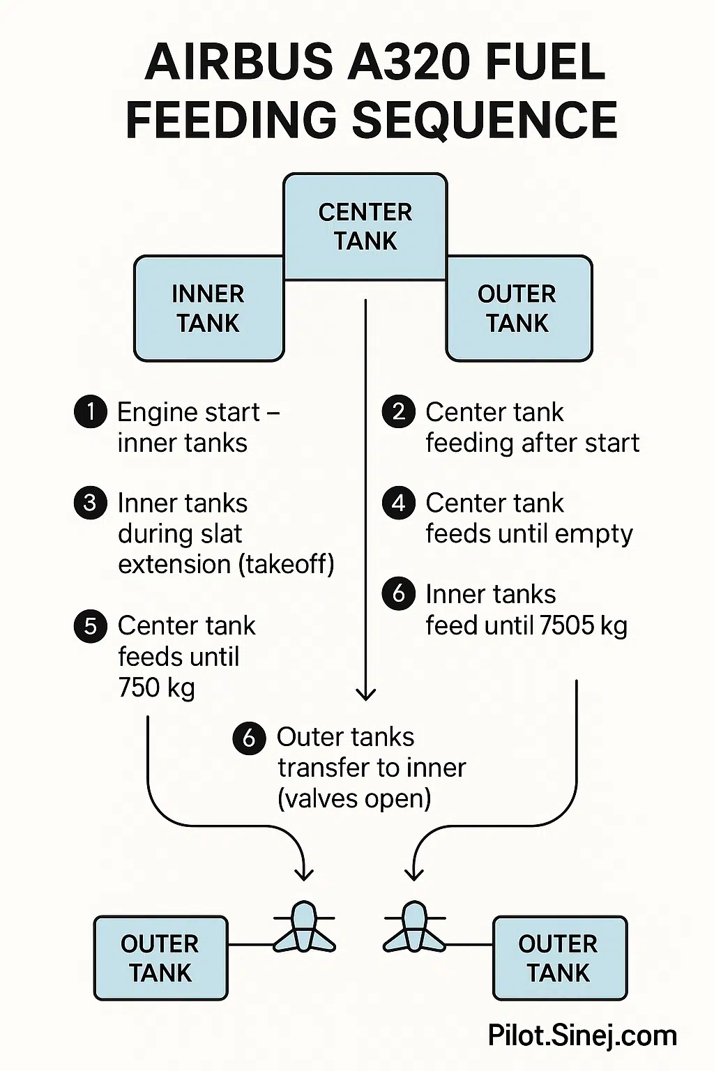
Step-by-Step Fuel System Feeding Sequence Explained
1. Engine Start: Inner Tanks Only
When starting the engines, the aircraft draws fuel from the inner wing tanks.
2. After Engine Start: Switch to Center Tank Feeding
Shortly after both engines are running, the system begins feeding from the center tank, if fuel is available there.
3. Takeoff Configuration: Return to Inner Tanks
To prevent center tank feeding during takeoff, the system switches back to inner tanks when slats are extended during taxi-out.
4. Post Takeoff: Center Tank Resumes
Once slats are retracted after takeoff, center tank feeding resumes and continues until the tank is fully empty.
Fuel Recirculation & Return Flow
Not all the fuel sent toward the engines is burned. Some of it is used to cool:
- Integrated Drive Generator (IDG)
- Fuel-Cooled Oil Cooler (FCOC)
This fuel returns to the outer tanks. If they are full, excess flows via spill pipes into the inner tanks.
FLSCU (Fuel Level Sensing Control Unit) monitors tank levels and controls feeding logic accordingly.
Smart Feeding Cycle
- Feeds from center tank
- If inner tanks are full, center tank feeding stops
- ~500 kg used from each inner tank to make space
- Center tank feeding resumes
This cycle repeats until the center tank is empty.
 Feeding from Inner Tanks Until Low Level
 Feeding from Inner Tanks Until Low Level
Engines continue to feed from inner tanks until the fuel level drops to ~750 kg. At this point:
- Transfer valves open
- Outer tanks drain into inner tanks
- Valves remain open until next engine start
Why Outer Tanks Are Used Last
Outer tanks have no pumps. This design:
- Maintains fuel near the wingtips
- Reduces wing bending moments
- Prevents flutter
Summary Chart: A320 Fuel Feeding Order
| Phase | Fuel Source | Trigger/Event |
|---|---|---|
| Engine Start | Inner Tanks | Manual/Automatic |
| After Engine Start | Center Tank | Auto-switch after start |
| Takeoff Config (Taxi) | Inner Tanks | Slat extension |
| After Takeoff | Center Tank | Slat retraction |
| Center Tank Empty | Inner Tanks | Fuel level monitoring |
| Inner Tanks Low (~750 kg) | Outer Tanks drain to inner | Transfer valves open |
| Final Feed | Inner Tanks (combined) | Until fuel exhaustion |
What Pilots Should Remember
- Center tank feeding is prohibited during takeoff
- FLSCU logic prevents tank overfill
- Outer tanks draining = approaching final reserve
- Transfer valves stay open until next engine start
- Always monitor the ECAM fuel page
Related Topics to Explore
- How to Read the A320 ECAM Fuel Page
- A320 Fuel System – Skybrary Aviation Safety
- Understanding the Fuel Level Sensing Control Unit (FLSCU)
Final Thoughts
The A320’s fuel system is a masterclass in automation and safety logic. Whether you’re preparing for a type rating, teaching others, or just geeking out over aircraft systems, understanding the fuel feeding process deepens your appreciation for how smart this aircraft really is.
Got a question? Leave a comment or connect with us at Pilot.Sinej.com.
Infographic available below – showing the complete visual sequence of the A320 fuel feeding process.