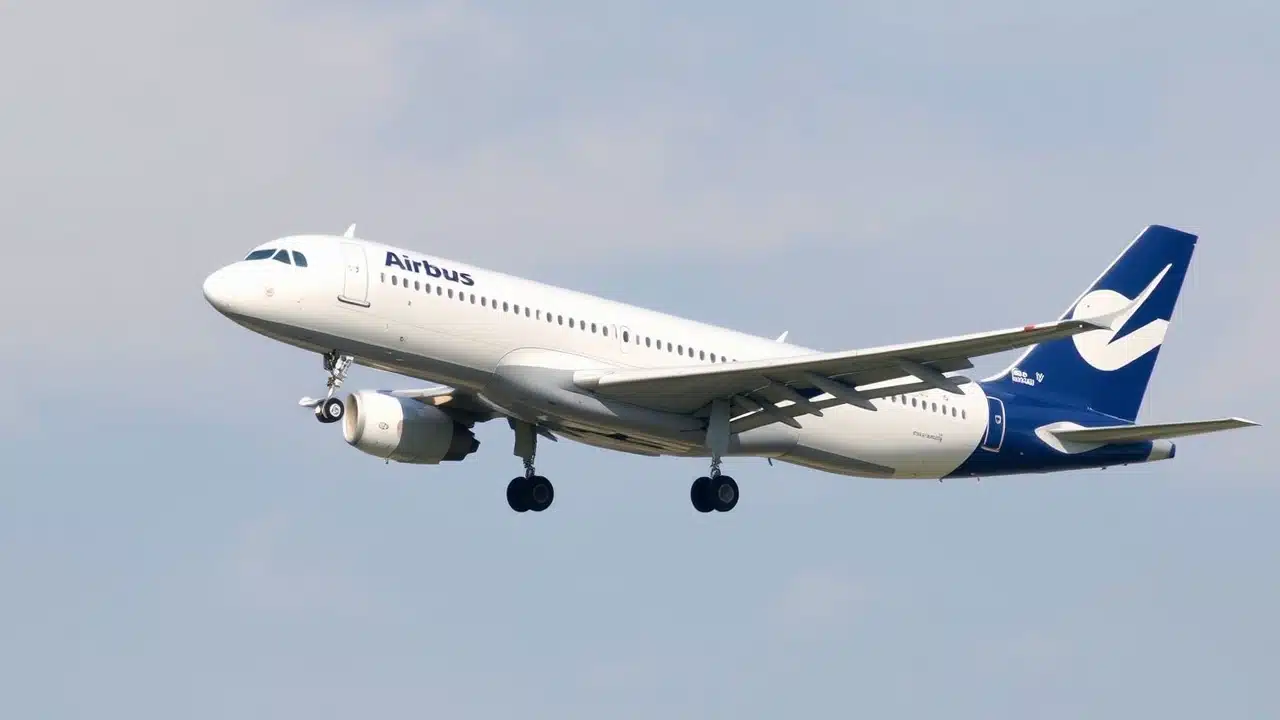
Join us as we explore in detail the Speed Reference System (SRS) of the Airbus A320. This sophisticated automated technology is essential during two crucial flight phases – takeoffs and go-arounds. Pilots must thoroughly comprehend the SRS to maintain safety and operational efficiency.
In this discussion, we’ll examine the system’s functionality and highlight its significance in contemporary aircraft operations.
Understanding the Airbus A320 Speed Reference System (SRS)
 What is the Speed Reference System (SRS)?
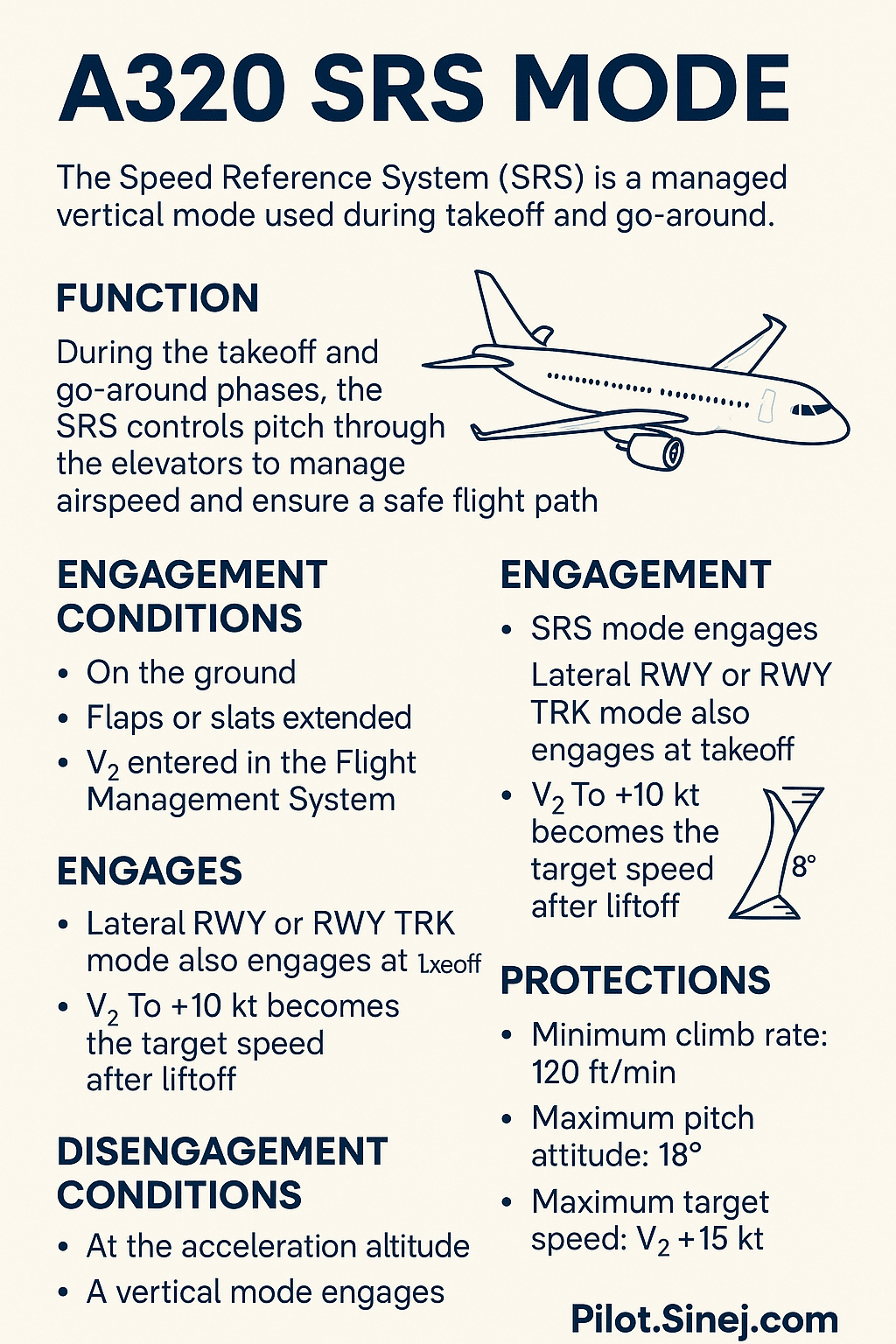
The Speed Reference System, or SRS, is a managed vertical mode on the Airbus A320. The SRS mode is primarily used during takeoff and go-around procedures. The SRS TO controls the aircraft speed using the elevators to maintain the aircraft on a flight path. Similarly, the SRS GA controls the speed target via the elevators during a go-around.
Key Components of the SRS
The SRS guidance law incorporates several protective measures. First, a flight path angle protection ensures a minimum vertical speed of 120 ft/min during takeoff and a positive climb during go-around. Additionally, pitch attitude is protected with limits (normally up to 18°, 22.5° in windshear) to reduce the nose-up effect during takeoff. Finally, there is also a speed protection that limits the speed defined by the SRS to V2+15 kt during takeoff, and that also ensures the aircraft does not exceed VFE during go-around.
Importance of SRS in Flight Safety
The Speed Reference System is vital for flight safety because it provides automated SRS guidance during critical phases. By managing speed and flight path, the SRS enhances pilot workload management. Speed control, attitude protection, and minimum climb gradient assurances are some of the safety features within the system. Also, pilots can ensure safe and consistent performance, especially during high-workload situations like takeoff and go-around.
How SRS Mode Works During Takeoff

When SRS TO engages (conditions)
SRS TO mode engages when certain conditions are met. The aircraft must be on the ground with slats or flaps extended. V2 must be inserted in the PERF TAKEOFF page. And the flight crew must set at least one thrust lever to the TOGA detent, or to the FLX-MCT detent, when a FLX TO temperature or a Derated Takeoff is entered in the PERF TAKEOFF page. When these conditions are met, the SRS is armed and ready for takeoff.
Role of V2 and managed speed targets
When the aircraft is on the ground, V2 becomes the initial speed target defined by the SRS guidance. As soon as V2 is inserted, or SRS TO mode engages, the speed automatically becomes managed. This means the flight director commands are based on maintaining V2 during the initial phase of the takeoff. This managed speed simplifies pilot workload, allowing them to focus on other critical aspects of the takeoff.
Pitch angle protections (normally up to 18°, 22.5° in windshear)
The SRS guidance law includes a pitch attitude protection. This reduces the aircraft nose-up effect during takeoff. The maximum pitch attitude is limited to 18 degrees under normal conditions and up to 22.5 degrees in windshear. This protection prevents excessive pitch angles that could compromise safety or lead to a stall during takeoff.
V2 → V2+10 target after liftoff
After liftoff, the target speed becomes the higher of V2+10 kt. So, once the aircraft becomes airborne, the speed target transitions from V2 to V2+10 knots. This increase in target speed ensures a safe climb gradient and provides a buffer above the stall speed. This managed speed increase is another feature of the SRS designed to enhance safety during the critical initial climb phase.
What happens during engine failure: target speed frozen, bounded by V2 and V2+15
In the event of an engine failure, the speed target becomes the higher of the current speed at the time of failure detection. However, the speed target is limited by V2 and V2+15 kt. This feature ensures that the aircraft maintains a safe speed even with one engine inoperative. This design is to prevent the aircraft from either slowing down too much or exceeding operational limits following the engine failure.
RWY mode integration
At takeoff, SRS vertical mode and RWY lateral mode simultaneously engage. The RWY mode guides the aircraft along the runway centerline, while SRS at takeoff maintains the appropriate speed and climb gradient. After that, in some cases, when airborne, RWY mode can change to another lateral takeoff mode such as RWY TRK mode. This integration of vertical and lateral guidance ensures a smooth and controlled takeoff.
How SRS Mode Works During Go-Around
 How and when SRS GA engages (TOGA thrust, flaps ≥ 1, airborne)
SRS GA mode engages when the flight crew sets at least one thrust lever to the TOGA detent, the flaps lever is at least in position 1, and the aircraft is airborne or on ground for less than 30 seconds. This mode can be engaged regardless of the vertical mode, except SRS TO. The speed reference system then transitions to guiding the aircraft through the go-around.
Speed target: higher of VAPP or speed at GA initiation
The speed target defined by the SRS guidance is the higher of the memorized aircraft speed at SRS GA engagement or VAPP. The upper limit of the target speed is the lowest value between 25 knots above VLS, or 15 knots above VLS when one engine is inoperative, and 5 knots below VMAX. Ensuring speed defined by the SRS is within limits is critical for a safe go-around.
Protections against excessive pitch, FPA, VFE exceedance
The SRS guidance law includes a flight path angle protection to ensure a positive climb. It also has a pitch attitude protection to reduce the aircraft nose-up effect, limiting the maximum pitch attitude to 18 degrees, or 22.5 degrees in case of windshear. There is also a speed protection that ensures the aircraft does not exceed VFE. The speed reference system is designed to keep the aircraft within safe operational parameters during the go-around.
Disengagement conditions
The SRS mode disengages automatically based on certain conditions. It’s designed to transition control back to the flight crew when appropriate. This ensures a balance between automated assistance and manual control, optimizing safety and efficiency during critical phases of flight, especially during takeoff and go-around procedures.
When and How SRS Disengages
 Acceleration altitudes (ACC ALT / GA ACC ALT)
SRS TO mode disengages automatically at the ACC ALT. The SRS GA mode disengages at the go-around acceleration altitude, or if ALT* or ALT CST* mode engages above 400 feet RA. These altitude thresholds are crucial for transitioning from the automated SRS to other vertical modes, ensuring a smooth and controlled flight progression.
ALT*, ALT CST*, OP CLB engagement
SRS TO mode disengages automatically if ALT* or ALT CST* mode engages above 400 feet RA, or if another vertical mode engages. The SRS GA mode disengages if the flight crew engages another vertical mode. These transitions allow pilots to manage the aircraft using different automation levels as the situation evolves, ensuring optimal control and awareness during the go-around or climb phase.
Engine-out caveats
In Engine Out conditions, the SRS mode does not automatically disengage at EO ACCEL ALT. Pilots must be aware of this difference and manually manage the aircraft accordingly. This is to account for the reduced performance and unique handling characteristics of the aircraft with an engine inoperative, maintaining safety during critical flight phases.
Reversions explained (to OP CLB) with triple click + boxed mode + FD flash
SRS TO reverts to OP CLB when the FCU selected altitude is above the aircraft altitude, and the flight crew pulls the SPD/MACH knob. When the reversion occurs during takeoff, a triple click sounds, the new guidance mode is boxed for 10 seconds, and the flight director bars flash for 10 seconds. The same occurs when SRS GA reverts to OP CLB, with the triple click and boxed mode indication. This alerts the flight crew to the change in automation and ensures they are aware of the new vertical mode.
Common Misunderstandings About SRS
SRS ≠ SPD mode
It’s a common mistake to equate the SRS mode with the standard SPD vertical mode. The speed reference system is specifically designed for takeoff and go-around, while SPD mode is a general speed control vertical mode used during other phases of flight. The SRS is a highly specialized automation tool that the flight crew utilizes. Remember, SRS mode controls pitch to maintain the target speed, a key difference from other vertical modes.
Why managed speed is tied to V2 entry
The reason the managed speed is tied to V2 is because V2 is the minimum safe takeoff speed. By using V2 as the initial speed target defined by the SRS guidance, the speed reference system ensures the aircraft has adequate performance in case of an engine failure during takeoff. Inserting V2 arms the SRS mode and allows the automation to protect the aircraft at a critical phase of flight. Without V2, SRS cannot engage.
Misconception: SRS only provides pitch angle — it’s about energy management too
Many think the SRS only manages pitch attitude, but it’s fundamentally about energy management. The SRS guidance law integrates speed, attitude protection, and flight path angle to ensure the aircraft maintains sufficient energy to safely complete the takeoff or go-around. It’s about keeping the aircraft within a safe operational envelope, considering factors like altitude, current speed, and engine performance. The SRS at takeoff is a holistic tool.
 Conclusion and Summary
Recap of SRS Importance
The Airbus A320 SRS (Speed Reference System) is critical during takeoff and go-around procedures. When initiated, the thrust levers are set to the TOGA position, activating SRS mode, visible on the FMA (Flight Mode Annunciator). During takeoff, the speed target becomes the highest of V2 plus a margin, ensuring optimal angle of attack for climb performance.
The aircraft will remain in SRS mode until 1500 ft RA or until an altitude constraint (ALT CSTR) from the flight plan is reached. Once these conditions are met, SRS reverts to OP CLB mode automatically, transitioning to normal climb operations. If in managed mode, the system follows the path in the vertical plan at a speed defined by performance parameters.
During a go-around, the thrust mode immediately changes as crew selects a speed target or allows the auto flight system to manage the flight envelope. If the pilot activates CLB mode or an ALT CST is encountered, the aircraft transitions out of SRS. Pilots must thoroughly understand how to deal with the SRS system to ensure safe operations during these critical flight phases.
Future of SRS in Modern Aviation
The future of the speed reference system in modern aviation involves further integration with other automation systems and enhanced predictive capabilities. As technology advances, we can expect the SRS to become even more sophisticated in its ability to manage energy, adapt to changing conditions, and provide pilots with intuitive guidance. Innovations will continue to optimize the Airbus A320’s safety and efficiency through improvements to the SRS.
Video: A320 Takeoff Explained
Final Thoughts on Airbus A320 Operations
The SRS is an invaluable asset in ensuring safe and efficient Airbus A320 operations. As flight crew, maintaining proficiency in its use, understanding its limitations, and staying updated with the latest advancements is paramount. The speed reference system is a testament to the continuous innovation in aviation, designed to support pilots and enhance the safety of air travel, so be sure to master the SRS.
People Also Ask
What are the key parameters that influence the SRS calculations for safe flight?
The SRS mode manages pitch to maintain a target speed and ensure a safe flight path during takeoff and go-around. Key parameters influencing its behavior include:
-
V2: The engine-out takeoff safety speed, used as a reference.
-
V2+10 knots: The default airborne speed target after liftoff.
-
Current speed at engine failure: In engine-out scenarios, SRS locks to this speed (bounded by V2 and V2+15).
-
Flap/slat configuration: Needed for mode engagement and affects pitch limit protections.
-
Pitch protection logic: Caps pitch at 18°, or 22.5° in windshear.
-
Minimum vertical speed: Maintains at least +120 ft/min for safe climb gradient.
These values are calculated in real time based on the FMS takeoff configuration, air data, and flight control laws.
How does the SRS differ from other speed management systems in aircraft?
SRS is unique in that it's a managed vertical guidance mode, not simply a speed target controller:
-
SRS controls pitch, not thrust, to maintain the target airspeed — unlike autothrust systems.
-
It automatically engages under specific conditions (e.g., TOGA detent and flap configuration).
-
It's active only during takeoff or go-around, whereas other modes like OP CLB or V/S are used in climb/cruise.
-
SRS has built-in protections — it prioritizes safe climb, vertical path, and energy management over just tracking a numerical speed.
In contrast, other systems like V/S (Vertical Speed) or FPA (Flight Path Angle) modes allow the pilot to manually select flight path parameters without these embedded protections.
What operational scenarios could lead to the activation of the SRS during flight?
SRS activation can occur in these scenarios:
-
Takeoff: Upon thrust lever set to TOGA or FLX/MCT (if FLEX temperature is entered), slats/flaps extended, and V2 entered.
-
Go-Around: During an approach or after touchdown (within 30 seconds), if the TOGA detent is selected and flaps ≥ 1.
-
Windshear escape: If TOGA is selected in response to predictive or reactive windshear alerts, SRS provides pitch guidance while maintaining safe climb speed.
-
Missed approach: Triggered intentionally by the pilot during approach when visual cues are not sufficient.
SRS will not activate mid-cruise or descent — it's strictly linked to critical flight phases involving terrain clearance and energy safety.
How does pilot input interact with the SRS during takeoff and go-around maneuvers?
Pilot interaction with SRS is indirect but essential:
-
Thrust lever movement: Sets the condition for SRS to engage (TOGA or FLX/MCT).
-
Rotation: The pilot manually rotates the aircraft to follow the Flight Director (FD) pitch bar, which reflects SRS guidance.
-
FMA monitoring: Pilots confirm “SRS” is displayed on the FMA during both takeoff and go-around to validate correct engagement.
-
Speed monitoring: While SRS is managing the pitch, pilots still monitor speed trends to guard against unexpected decay or acceleration.
-
Reversion logic: If the FCU altitude is above the aircraft and the pilot pulls for OP CLB, SRS reverts — this must be managed actively.
In short: pilots don’t “fly the SRS” manually, but they follow its guidance via the flight director — with override authority always available.
What are the consequences of SRS malfunction during takeoff or go-around?
If SRS fails to engage or malfunctions:
-
Loss of automatic pitch guidance: Pilots must fly manually without the FD bar, using procedural pitch targets (e.g., 15° for all-engine, 12.5° for EO).
-
Increased workload: Especially critical in single-engine or low-visibility go-arounds.
-
Possible deviation from optimum energy management: Could lead to under-speed or unsafe climb if not immediately corrected.
-
Abnormal ECAM indications: May show FMGC or FCU faults affecting mode logic.
While rare, SRS non-engagement is trained for in sim sessions. Pilots revert to raw pitch-and-power flying — a skill that remains vital during such anomalies.
How does the SRS interface with other avionics systems on the Airbus A320?
SRS mode integrates tightly with several avionics and autoflight components:
-
Flight Management and Guidance Computer (FMGC): Calculates and commands SRS pitch targets, V2 values, and speed limits.
-
Autopilot/Flight Director System (AP/FD): Displays SRS commands on the PFD via FD bars; autopilot can follow them if engaged after liftoff.
-
Autothrust System (A/THR): Works in parallel — while SRS controls pitch, A/THR ensures correct thrust based on detent and speed trends.
-
Air Data Inertial Reference Unit (ADIRU): Supplies airspeed, pitch, and vertical speed inputs to refine SRS commands.
-
FMA (Flight Mode Annunciator): Displays SRS engagement on the PFD, critical for pilot awareness and mode verification.
This multi-system synergy ensures that SRS provides robust, protected vertical guidance during the most demanding phases of flight.